Published: June 28, 2022
Modified: December 12, 2024
Table of Contents
Linear Regulator
Operation of Linear Regulator
Advantages and Disadvantages of Linear Regulators
Types of Linear Regulators
In our daily lives, we seldom hear the word "linear regulator". However, it is one of the electronic components that is commonly used in electronic products around us, including PCs and smart phones that you are using to read this page right now.
Linear Regulator
A linear regulator is a type of device that can output a constant voltage without being affected by fluctuations in input voltage, the current consumption of application devices, temperature, or time. It is also called a voltage regulator. Compared to a switching regulator, which is also a type of regulator, the power conversion efficiency of linear regulator is inferior because it controls the voltage while converting and releasing the power energy into heat. On the other hand, the output voltage is very stable and noiseless, and you can configure a power supply circuit easily with a linear regulator because it requires fewer external components compared to a switching regulator.
In recent years, due to the increasing demand for low power consumption of electronic devices, switching regulator with excellent conversion efficiency have become the mainstream when constructing power supplies with high power output. However, when constructing power supplies for applications with strict noise and mounting area requirements, linear regulators with simple configuration and low noise still have many opportunities to be used.
There are two types of linear regulators depending on how the output transistor, or the variable resistor, is inserted: the series method (inserted in series between the input and the load) and the shunt method (inserted in parallel with the load). However, since the shunt method has limited applications, this article will focus on the series method only. From now on, I will use some technical terms in circuit design to explain the logic of the operation.
Operation of Linear Regulator
The simplest linear regulator is called a three-terminal regulator, which has three terminals (pins): input, output, and GND. The chip enable (CE) pin, which controls the ON/OFF of the chip operation itself, has been added to the regulator, and now there are many products with four or more pins.
Now let's take a look at what is inside it. Generally, a linear regulator consists of a negative feedback control circuit with four components: an output driver transistor, a feedback resistor, a reference voltage source, and a differential amplifier (error amplifier). To this circuit, a linear regulator is completed by simply adding one capacitor on the input side and another on the output side for phase compensation. Isn't it easy?
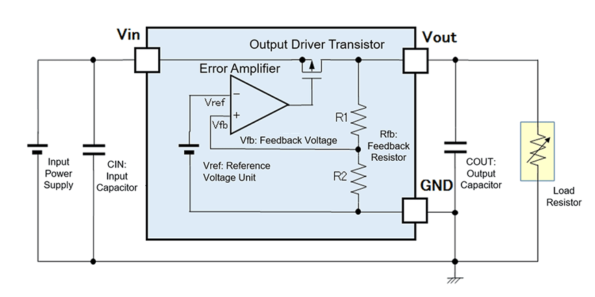 Figure 1. Circuit Diagram of a Linear Regulator
Among the four components mentioned above, the output driver transistor, which behaves like a variable resistor, is finally responsible for converting the input voltage into a constant output voltage. As the name implies, a variable resistor is a resistor that can change its resistance value. The output voltage of the linear regulator is maintained at a constant voltage level by fine-tuning the resistance value with the feedback of the output voltage.
The following figure shows the output characteristics of a linear regulator. The reason that this type of device is called a linear regulator is because it outputs the input voltage in a linear manner.
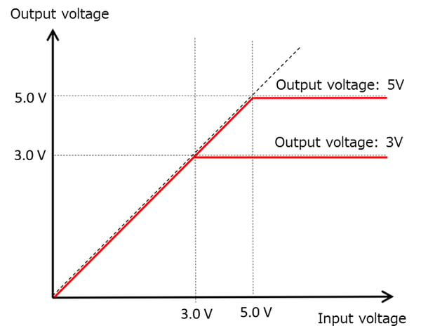
Figure 2. Output Characteristics of Linear Regulator
The principle of its voltage conversion is based on Ohm's Law, familiar to us from junior high school science textbooks, and the following formula can be used to calculate resistance and power consumption.
Resistance = Voltage / Current
Voltage = Current × Resistance
Ohm's law
Advantages and Disadvantages of Linear Regulators
Now, I would like you to remember an experiment we did in junior high school. While the current is flowing, a resistor emits heat. This heat means that some of the input power has been consumed as heat.
In fact, the linear regulator has a disadvantage that the conversion efficiency tends to be low because the unnecessary power is consumed as heat. In particular, the larger the difference between input voltage and output voltage (input-output voltage difference), the more obvious this tendency becomes. In addition, if the heat generation exceeds a certain level, it will lead to the failure of the electronic equipment, so thermal design is very important with the allowable package power dissipation of the IC taken into consideration.
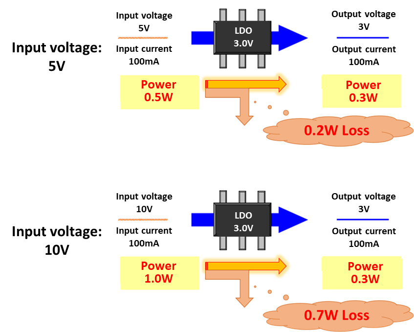
Figure 3. Losses when Inputting 5 V and 10 V to a 3 V Output Regulator
While there is a disadvantage of low conversion efficiency, there is of course an advantage. In addition to the above-mentioned simple circuit configuration and easy to reduce the mounting area, the merit of the linear regulator is that the output voltage has less unnecessary frequency factors (noise). Therefore, for noise-sensitive devices such as audio, a power supply configuration with a linear regulator is often used to remove noise from the voltage from a switching regulator, which has high conversion efficiency but has noise.
Types of Linear Regulators
Linear regulators can be classified according to the configuration of the output driver and the circuit configuration to ground. When the linear regulator first came into use, an NPN Darlington configuration using multiple NPN transistors was the standard.
However, Darlington type linear regulators have various drawbacks in terms of efficiency of voltage conversion, such as large lower limit of dropout voltage, which is the minimum requirement of voltage difference between input and output voltages, large resistance value, large power (current) required to operate (in other words, discarded power that must be released is large).
With the development of technology and the emergence of portable battery-powered devices such as cell phones and notebook PCs, linear regulators that can convert voltage with low consumption and high efficiency are required to ensure that these devices can operate for a long time. Therefore, the low dropout voltage regulator, or LDO regulator, which can suppress power loss by reducing the difference between input voltage and output voltage (input-output voltage difference), has become a major product.
Today, the demand for low power consumption has become even stronger, and CMOS LDO regulators that can achieve low power consumption are playing an increasingly important role.
Table 1. Classification of Linear Regulators
|
Classification of Linear Regulators |
Circuit |
Advantages |
Disadvantages |
|
Bipolar Standard Type |
An output driver transistor consists of a multiple NPN transistors. (called a Darlington configuration) |
Smaller ground current. Suitable for high load current. Large maximum input voltage. |
High dropout voltage, around 2 to 3 V. Power efficiency is not good. |
|
Bipolar LDO Type |
An output driver transistor consists of PNP transistors. |
Smaller dropout voltage than bipolar standard type (about 0.5 to 0.8V) |
Large ground current. An output capacitor is required for stability. |
|
CMOS LDO Type |
CMOS transistors, which use n-type and p-type FET, are used to construct the main circuits, including the output driver, differential amplifier, and reference voltage source. |
Low dropout voltage (around 0.1V to 0.4V). Self-consumption current is very low. As a result, the conversion efficiency is better. |
Due to high output impedance, fast response was not good, but not so much anymore with the advancement of technology. |
To be continued next time





Comment