

This story is about a circuit to switch the backup power supply of a real time clock IC (RTC).
One day, Bunta, a third-year fresh employee, comes to Atsuo, a veteran, with an annoyed look.
*Click here to read the previous blogs in the "Help Me, Senpai! series":
Vol. 1 IoT for Energy Harvesting: Solar Panel Can’t Drive System till Morning…
Vol. 2 Stop Sleeping Mobile Device from Consuming Battery Charge!
Help Me, Senpai! Series Vol. 3
RTC Backup Switchover Circuit Is Not Easy.
 Rookie B
Senpai! It’s a big hassle to make a power supply switchover circuit.
 Senpai A
Come on... That’s your business, right?
 Rookie B
As a real time clock must operate continuously, it is necessary to switch the power supply properly. Constructing such a circuit is too much work.
| *Real Time Clock: An IC having a clock function. It literally keeps time by a backup power supply after the system power supply turns off. It is abbreviated RTC. |
Senpai A
In particular?
Rookie B
A lithium-ion secondary battery pack is the main power supply. The system charges the battery via USB, and the RTC must be backed up by a coin battery as a last resort if the main power supply stops. I’m considering how to switch the power supply line.
Senpai A
You can do it with a simple, basic circuit, isn’t it? Why don’t you use a “diode OR circuit”?
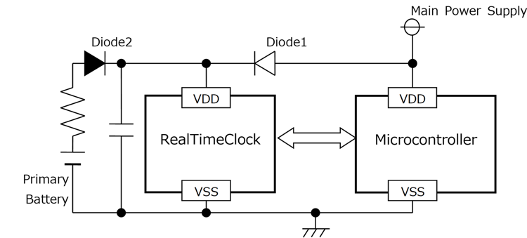 Figure 1. Backup Switchover Circuit Using Diode OR Circuit
Rookie B
I know what you mean, but... A diode causes voltage drop and large leak current. It bothers me.
Senpai A
Sure. Using a real time clock IC means that you are concerned about current consumption. It’ll be a problem that a leak current occurs at the backup switchover circuit. Plus, more and more leak current flows as the temperature of the diode increases, so diodes are not suitable for backup batteries...
Rookie B
Besides, when the voltage of a battery pack drops, it's reversed with the voltage of a coin battery, right? Then the battery pack will be charged by the coin battery even though the charge is still left in the battery pack. This is meaningless, isn't it?
 Senpai A
That's not good. But the voltage of a coin battery is fixed. ......
 Rookie B
It’s a hassle, isn’t it? The thing is, a simple switchover circuit may do since the device won’t be left with its battery uncharged, I think... It is often the case that the clock is reset because of the device being left, so I don’t think it should be backed up for such a long time...
Senpai A
Hahaha, hey, don’t tell me such a thing. You mustn’t compromise in such a negative manner.
By the way, there is a real time clock IC having a battery backup switchover circuit.
Real Time Clock IC with Backup Switchover Circuit?
 Rookie B
Here! You know the answer! Why not tell me earlier!?
Senpai A
Hey, man... Anyway! This IC contains a circuit to switch between main and backup power supply lines. Since the backup switchover circuit using a diode may cause a voltage drop, a large leak current and therefore is undesirable; the IC is conveniently equipped with a switchover circuit. There is no voltage reversal problem with the backup battery you mentioned earlier.
 Rookie B
That’s just what I said just a while ago! Then, how does the IC switch the lines?
Senpai A
A voltage detector circuit inside the RTC detects voltage drop and switches the power supply line. The following picture illustrates the concept. As you can see, there are three power supply pins.
Switching two power supply lines out of the three is the main usage. For example, a main power source is connected to the VCC pin, like an alternating current power (AC adapters) and USB power delivery. On the other hand, as a backup power source, primary batteries such as coin batteries are connected to the VSB pin and rechargeable ones such as secondary batteries and large capacitors to the VDD pin.
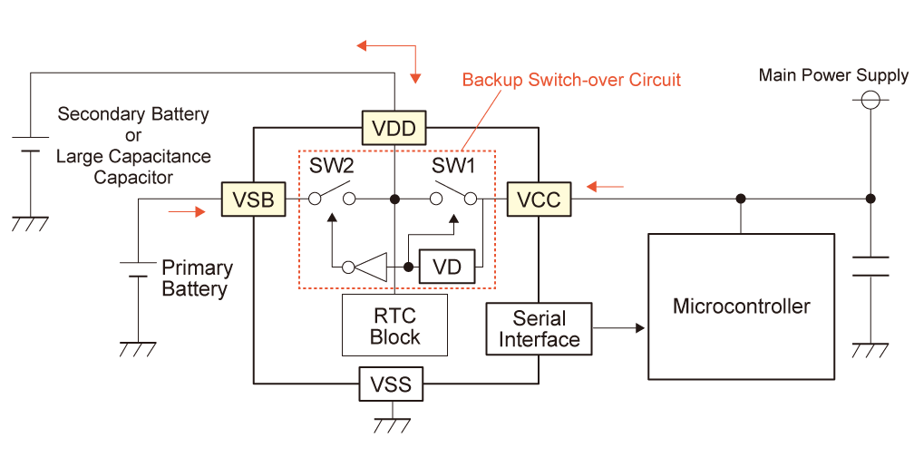
Figure 2. Block Diagram of Battery Backup Switchover Circuit
 Rookie B
How about battery packs? They are secondary batteries. Is it appropriate to connect them to the VDD pin?
Senpai A
Secondary batteries connected to the VDD pin are small-capacitance ones for backup such as coin-shaped batteries. Battery packs are used as a main power source, right? So, they are connected to the VCC pin.
 Rookie B
Although there are three power supply pins, two of them are used depending on the situation.
Senpai A
Right. Pins to be used are chosen by whether the backup battery is rechargeable or not. The VSB pin is for batteries that are not rechargeable such as coin batteries. When the main power supply is connected to the VCC pin, the VD (Voltage Detector) detects it and turns the SW1 on. At the same time, the inverter turns the SW2 off, so the coin battery connected to the VSB pin never depletes.

Figure 3-1. Example of Backup with a Coin Battery. Flow of Power from Main Power Supply (SW1: ON)
The VDD pin is for rechargeable small-capacitance secondary batteries and large-capacitance capacitors when they are used as a backup power. They can be charged if the main power supply works.
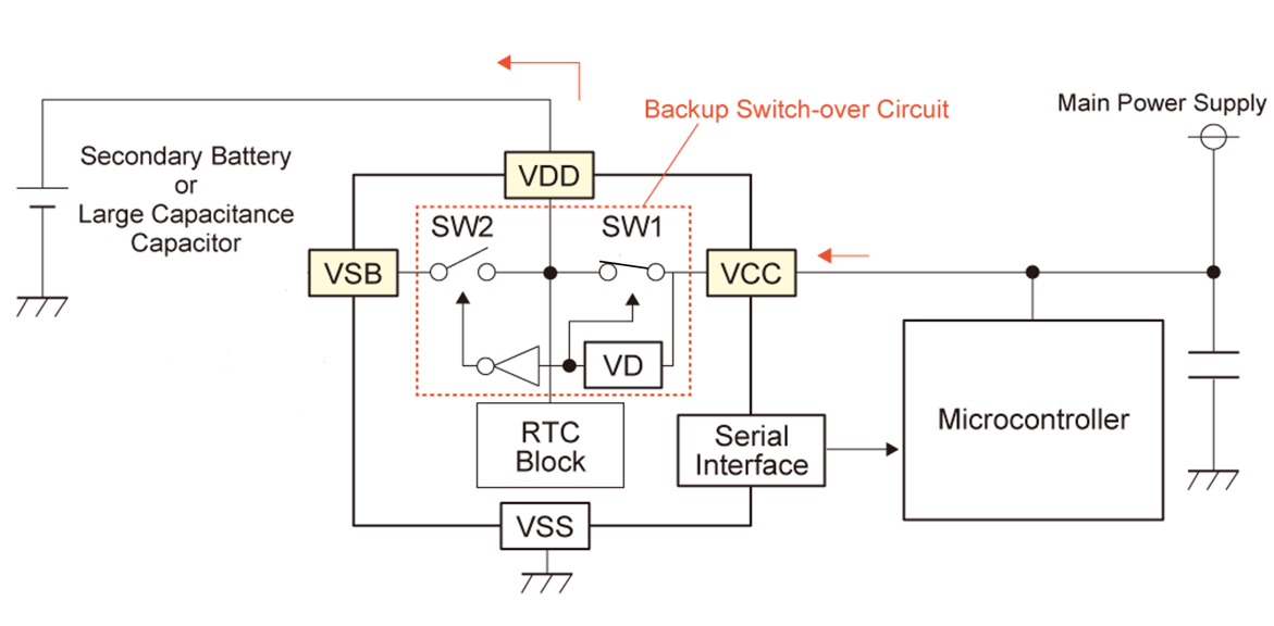
Figure 3-2. Example of Backup with a Secondary Battery or Large-Capacitance Capacitor. Flow of Power from Main Power Supply (SW1: ON)
 Rookie B
I see.
Senpai A
On the other hand, when the main power supply is disconnected from the VCC pin, the VD detects it and turns the SW1 off. At the same time, the inverter turns the SW2 on, so power flows from the coin batteries connected to the VSB pin. Thanks to this, the coin batteries won't be used up unnecessarily, will they?
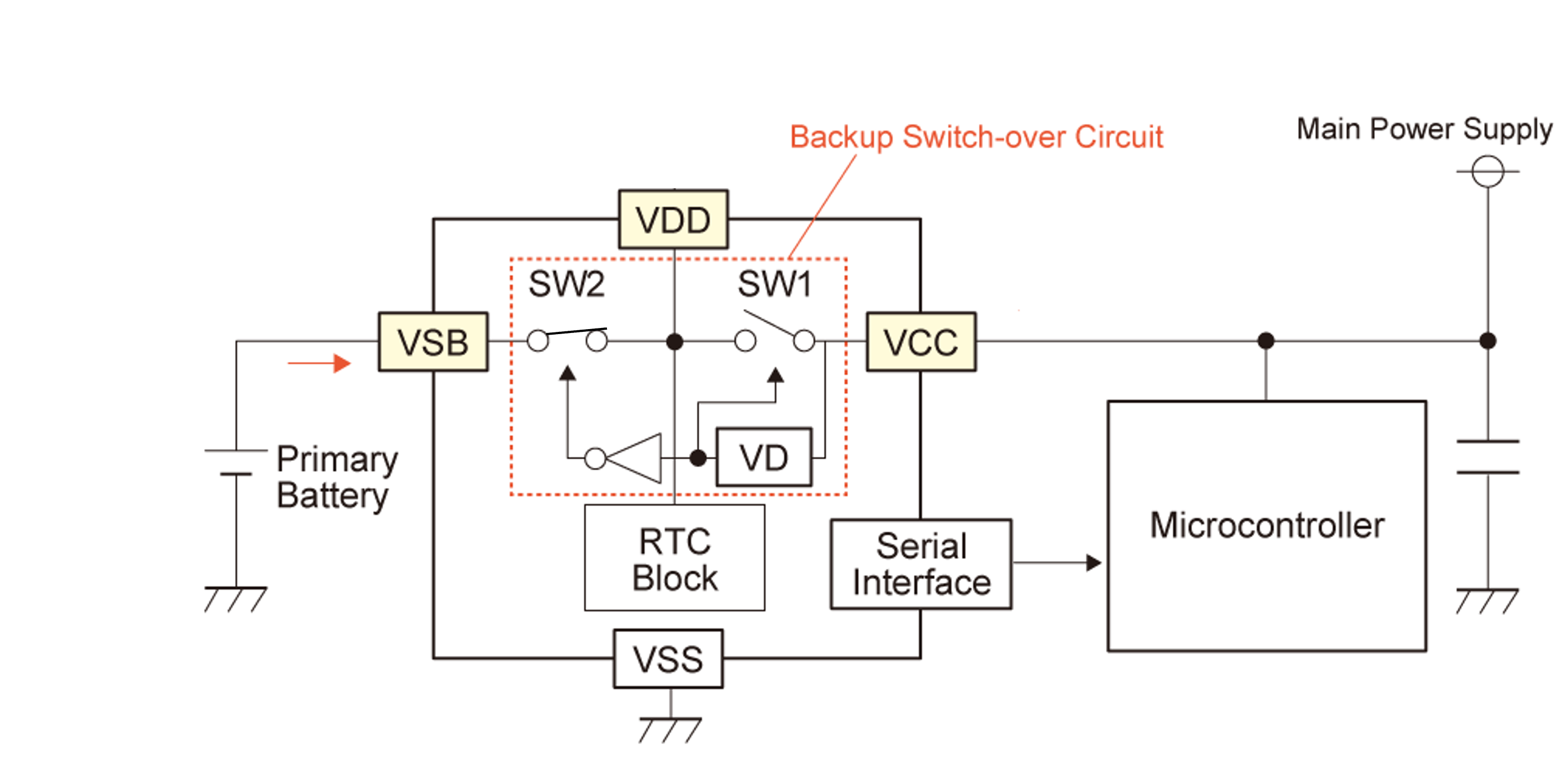
Figure 4-1. Example of Backup with a Coin Battery. Flow of Power from Backup Power Supply (SW2: ON)
When it is backed up with a secondary battery or large-capacitance capacitor, power flows from the secondary battery or large-capacitance capacitor connected to the VDD pin. In this way, by detecting the voltage of the VCC pin, it automatically switches the power supply lines.
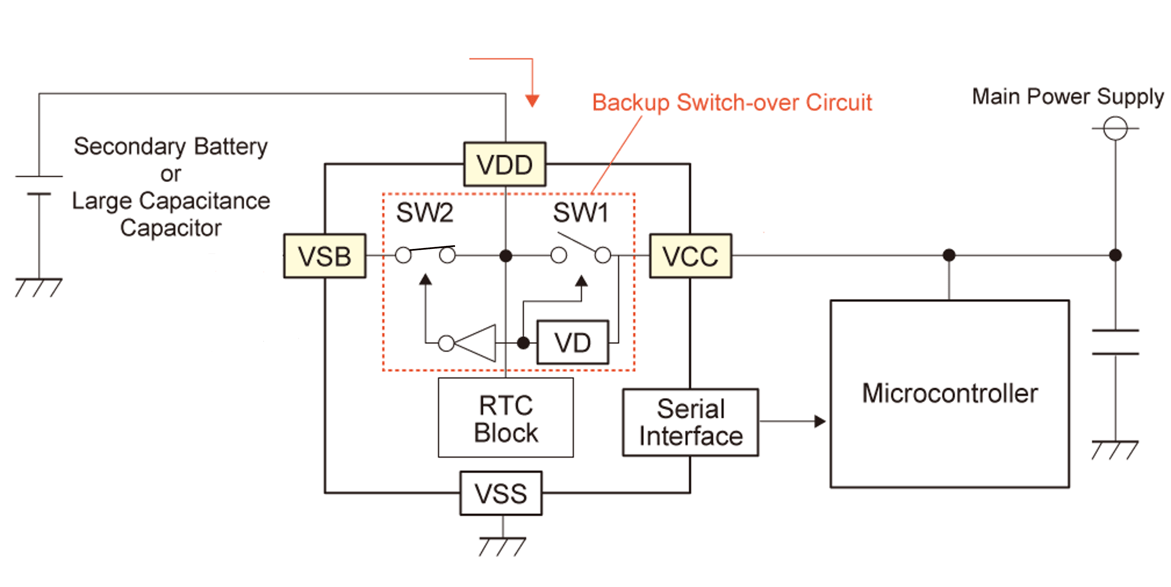
Figure 4-2. Example of Backup with a Secondary Battery or Large-Capacitance Capacitor. Flow of Power from Backup Power Supply (SW2: ON)
 Rookie B
Ah, huh. We can leave all the burden to the IC. A piece of cake!
Senpai A
Yeah, right, ha ha! No external components such as diodes are necessary, and a small mounting area is enough. There are many benefits.
 Rookie B
The way to use is the same with a normal real time clock, right?
Senpai A
Yeah, so it’s easy to use.
 Rookie B
Thank you. I will buy a sample and try it.
Senpai A
By the way, Nisshinbo Micro Devices (former Ricoh Electronic Devices) has provided real time clock ICs for a long time.
Long Established Manufacturer of Real Time Clock ICs?
 Rookie B
Uh, huh.
Senpai A
Once in a while, let me talk about an old story.
 Rookie B
Ha ha, I can’t help it.
 Senpai A
Originally, RTCs were for telephones, especially for telephone switchboards. Fees must be charged according to the duration of a call, such as 10 yen per 3 minutes of a local call.
Rookie B
Were they developed for telephone switchboards?
Senpai A
No, they were developed for facsimiles at first. Facsimiles charge fees according to the duration of communication via telephone lines, too.
Rookie B
I see.
Senpai A
The real time clocks were adopted to telephone switchboards and became the de facto standard.
Then, not only telephone switchboards but also other devices requiring clock display such as video cassette recorders adopted real time clocks.
Today, RTCs are used in many applications including phones, electricity, gas and water meters, electronic sphygmomanometers, etc.
 Rookie B
It’s amazing to have accumulated technology for such a long period. The company should make a pitch for it.
Conformity to Many Interfaces & Software Compatibility
Senpai A
Come on. RTCs at that time were parallel type and were replaced by serial type due to the evolution and speed improvement of interfaces.
To meet various interfaces, a wide variety of RTCs are prepared, such as two-wire type (for I2C bus), three-wire type, and four-wire type (SPI bus) which makes the ICs applicable to any MCU.
Rookie B
Surely, there are a lot of RTC products.
Senpai A
In addition, it is easy to replace one RTC for another with the same interface thanks to software compatibility.
Rookie B
I got it. Thank you.
I will buy some samples of the product with a backup switchover circuit and try it.
For more information about the battery backup switchover circuit, please click here.
A white paper will open.
List of Real Time Clocks with Battery Backup Switchover Circuit
Series Name Interface Package Note R2051x 2-wire (I2C bus) QFN023023-16, SSOP16, TSSOP10G R2262x 3-wire QFN0202-18, TSSOP10G Pins have different names. R2061x 3-wire QFN023023-16, SSOP16
Afterword
This is the third article of our serial contents introducing how our products help you.
If you have a question for us, please let us know.


Comment